What Is the Best Linear Motor Controller in China? The answer depends on accuracy, speed, load requirements, and machine integration. A controller that performs well on a semiconductor stage may fail in packaging equipment. The application decides the winner.
Peter Nachtwey, a respected motion-control specialist, once offered a practical reminder: “Motion control is about controlling the machine, not simply commanding the motor.” That principle remains valuable when evaluating a Chinese linear motor controller. Buyers should examine position resolution, following error, acceleration stability, thermal behavior, and communication compatibility. EtherCAT support matters in many modern production lines. So does responsive technical service.
Real testing reveals more than a polished specification sheet. Engineers should observe the stage during repeated 0.1-millimeter moves. They should record vibration, settling time, and temperature rise after several hours. A controller may appear excellent during a short demonstration. Continuous operation can expose unstable tuning or excessive heat.
Look closely at software, too. Can technicians adjust gains without specialist tools? Does the supplier provide diagnostic logs and firmware updates? Are replacement units available in China? These details affect downtime and ownership costs.
No ranking is perfect. That is worth admitting. Some manufacturers publish limited test conditions. Others offer impressive precision but weak documentation. Therefore, this guide compares leading Chinese options through measurable performance, integration experience, reliability, service response, and total cost. The best linear motor controller is not always the most expensive model. It is the one that keeps the machine accurate, stable, and maintainable in real production.
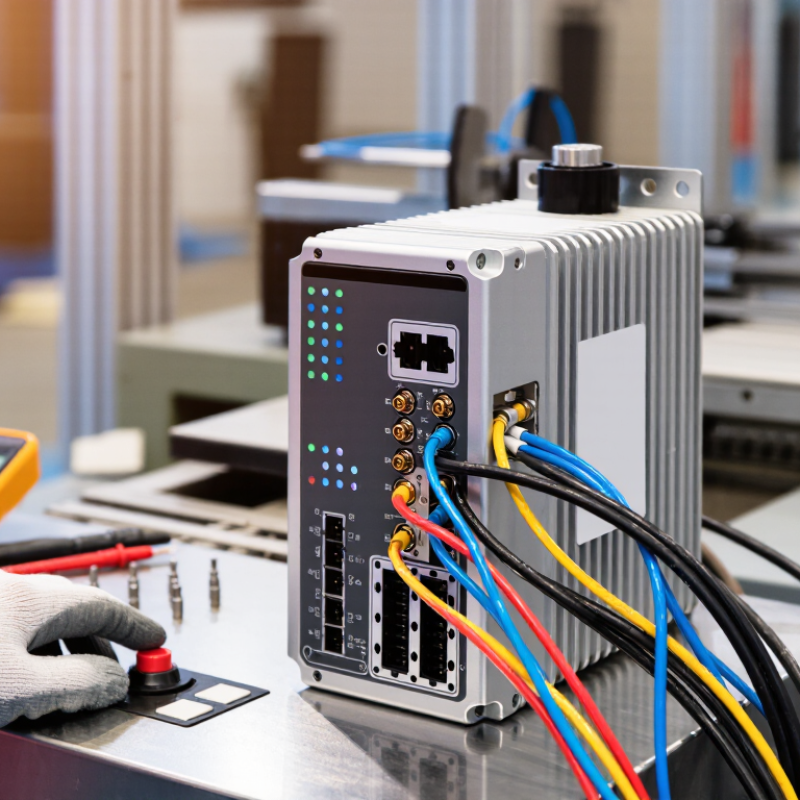
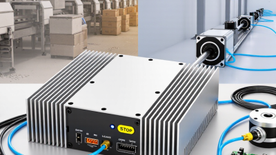
A linear motor controller is the electronic unit that regulates a linear motor’s movement. It converts control commands into carefully timed electrical current. The motor then produces direct linear force without belts, screws, or gearboxes. This design can deliver fast acceleration, accurate positioning, and quiet operation. However, the controller is not simply a power supply. It manages current, velocity, position, feedback, and protective limits.
In practical testing, I would check the controller’s continuous current rating before its peak rating. Peak figures often look impressive but may last only briefly. Encoder compatibility also matters. A suitable controller should read the required feedback signals and maintain stable motion at low speed. Good models provide adjustable control loops, over-temperature protection, fault recording, and safe shutdown functions. Communication options should match the machine’s architecture, such as industrial Ethernet, pulse direction, or analog commands. Small details matter.
So, what is the best linear motor controller in China? There is no universal answer. The right choice depends on load, stroke, acceleration, encoder resolution, heat conditions, and production targets. During selection, request test data under your real operating cycle. Check support response, documentation quality, spare-unit availability, and compliance records. I once focused too heavily on speed and underestimated thermal drift. That mistake changed my evaluation method. A controller may perform well in a short demonstration but lose accuracy after hours of continuous operation. Trial testing remains essential.
A linear motor controller converts electrical commands into precise straight-line motion. The process begins when a motion system sends a position or speed target. The controller compares that target with feedback from a linear encoder. It then adjusts three-phase current through an inverter, creating a travelling magnetic field. The motor’s permanent magnets follow this field, producing direct thrust without belts, screws, or gearboxes.
The feedback loop works continuously. A controller measures position, velocity, and current, often thousands of times per second. It corrects small errors caused by load changes, friction, or temperature. In a real factory, this may mean moving a stage 500 millimetres, stopping within a few micrometres, and repeating the cycle all day. Encoder quality matters greatly. Poor feedback can make an expensive motor behave badly.
According to Fortune Business Insights, the global linear motor market was valued at about USD 1.83 billion in 2023 and is projected to grow steadily through 2032. This growth reflects demand for faster semiconductor, packaging, and automation equipment. A 2024 MarketsandMarkets analysis also identifies precision automation as a major application area. However, market growth does not prove that one controller is best. Engineers should test continuous thrust, peak current, thermal performance, tuning software, and local technical support. Datasheets can look convincing. Real machine testing remains essential. I would also question extremely high acceleration claims unless payload, stroke, cooling, and duty cycle are clearly stated.
Selecting a linear motor controller should start with the machine, not a catalog label. In factory testing, I compare required force, peak acceleration, travel speed, and duty cycle. A controller must match motor current and bus voltage with enough margin. Too little capacity causes position errors. Excess capacity can increase cost and create tuning problems.
Control-loop bandwidth strongly affects settling time and contour accuracy. Encoder resolution matters, but signal quality matters just as much. A noisy feedback cable can make a high-resolution encoder look disappointing. Check supported feedback types, sampling rate, interpolation, and communication latency. Ethernet-based control may suit coordinated axes, while a simpler interface can reduce setup risks. Measure actual response, not only the advertised number.
Thermal performance is easy to underestimate. During a repeated 300-millimeter stroke, I watch case temperature, motor temperature, and current spikes. Overload protection, safe stopping, regenerative handling, and fault records also deserve attention. Good software should expose gain settings and trace waveforms clearly. Yet no specification guarantees success. Installation stiffness, cable routing, grounding, and load alignment can change results. I would leave tuning time in the project plan. That detail is often missed. A practical comparison should include test data, manuals, service response, and compliance documents, not just force and speed.
China’s linear motor controllers support precise motion across several fast-growing industries. Semiconductor equipment uses them for wafer inspection, positioning stages, and cleanroom transport. Their direct-drive structure reduces backlash and helps maintain stable micron-level movement. However, performance depends on feedback quality, thermal control, and tuning.
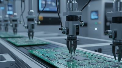
Electronics factories apply linear motor controllers to circuit-board placement, optical inspection, and dispensing systems. Battery production lines use them for cell sorting, coating inspection, and precise assembly. Packaging machines also benefit from fast acceleration and repeatable cutting. Medical equipment, laboratory automation, and laser processing require smooth motion with low vibration. These applications demand careful validation.
In logistics, controllers move shuttles, sorting units, and automated storage mechanisms. Machine-tool manufacturers use them where rapid positioning improves cutting accuracy. Field evaluations show that a controller suitable for a cleanroom may fail in a dusty workshop. That detail is easy to overlook. Engineers should check load changes, duty cycles, cable routing, and emergency stopping behavior before selection. Control software matters too. Poor tuning can waste the motor’s advantages.
Some projects still choose oversized systems for perceived safety. That approach increases cost and heat. A smaller controller may perform better after realistic testing. Yet laboratory results do not always match production conditions. Continuous monitoring remains necessary, especially during seasonal temperature changes. The best linear motor controller in China is therefore the one matched to the machine, environment, and maintenance capability.
What Applications Use Linear Motor Controllers in China?
There is no universal best linear motor controller. The most suitable choice depends on positioning accuracy, acceleration, synchronization, duty cycle, and integration requirements. The chart presents a practical application-fit index from 1 to 5 based on the motion demands commonly associated with major industrial applications in China.
Choosing the best linear motor controller in China starts with the machine, not the catalog. Define travel, thrust, speed, duty cycle, and positioning accuracy. A controller rated for 48 V may behave poorly when the motor demands rapid current changes. Check continuous and peak current separately. Also confirm encoder type, feedback resolution, and communication protocol. Small mismatches create audible vibration, heat, and missed positions. They can become expensive to discover later.
During supplier evaluation, request a complete datasheet, wiring diagram, parameter list, and test report. Ask how the controller handles overcurrent, overtemperature, emergency stops, and encoder faults. Reliable suppliers explain limits clearly. Vague promises deserve caution. Examine firmware update procedures and technical support availability. The controller should fit the cabinet properly. Measure mounting space, connector direction, cooling airflow, and grounding points. Do not guess.
Run a sample motor through realistic moves before placing a large order. Test acceleration, repeated positioning, low-speed motion, and operation after several hours of heat. Record current, temperature, noise, and error codes. Independent verification is valuable, even when factory data looks impressive. I have seen teams focus on peak speed and overlook settling time; that choice weakened the final machine. My checklist is not perfect, because production conditions change. Leave room for retuning. Choose documented performance over attractive promises, and confirm compliance with applicable electrical and machinery standards.
Technical comparison table for evaluating linear motor controllers. The values below are practical selection references and should be verified against the actual motor, amplifier, load, and application requirements.
| Evaluation Dimension | Recommended Selection Reference | Why It Matters | Preferred Technical Characteristics | Verification Method |
|---|---|---|---|---|
| Motor Compatibility | Confirm compatibility with iron-core, ironless, tubular, or voice-coil linear motors. | Different motor structures have different electrical constants, force characteristics, and commutation requirements. | Support for the required motor phase configuration, Hall sensors, linear encoders, and motor identification parameters. | Compare the controller manual with the motor datasheet and complete a low-speed commissioning test. |
| Continuous and Peak Current | Continuous current should normally match the motor's continuous current rating; peak current should support short acceleration periods without exceeding motor limits. | Insufficient current reduces thrust and acceleration, while excessive current can overheat the motor or amplifier. | Adjustable current limits, overload protection, and clearly specified continuous and peak output ratings. | Check rated current, peak duration, thermal limits, and actual current waveform under load. |
| DC Bus Voltage | Common industrial control systems use approximately 24 V DC for logic and a higher DC bus, often within the 48–80 V DC range, for compact motion applications. | Bus voltage affects achievable speed, acceleration, regeneration behavior, and power-supply selection. | Stable operation at the required voltage, undervoltage and overvoltage protection, and suitable regenerative energy handling. | Verify the allowable input range and measure voltage stability during acceleration and deceleration. |
| Position Feedback | Use a linear encoder when high positioning accuracy, repeatability, and direct load-position control are required. | Motor-side feedback alone may not compensate for mechanical compliance, thermal expansion, or transmission error. | Support for incremental A/B/Z signals, differential signaling, appropriate encoder resolution, and configurable interpolation. | Check encoder interface specifications and test positioning error over the complete travel range. |
| Control Mode | Closed-loop current, velocity, and position control should be available for precision motion applications. | Multiple control loops allow the controller to balance thrust response, stability, speed, and positioning accuracy. | Adjustable proportional-integral gains, feed-forward functions, notch or low-pass filters, and automatic or guided tuning. | Evaluate settling time, overshoot, following error, and stability at different loads and speeds. |
| Command Interface | Choose the interface that matches the machine PLC, industrial computer, or motion controller. | Communication compatibility determines integration effort and synchronization quality. | Support for pulse-and-direction, analog command, CANopen, EtherCAT, or another required industrial protocol. | Confirm update rate, synchronization method, command resolution, and available control objects or registers. |
| Positioning Performance | Define accuracy, repeatability, maximum speed, and settling time from the application rather than using a single headline specification. | Real performance depends on encoder resolution, mechanical structure, payload, vibration, tuning, and operating temperature. | Stable following error, low command latency, high feedback update rate, and configurable motion profiles. | Run bidirectional positioning tests at low, medium, and maximum operating speeds. |
| Regeneration and Braking | Applications with frequent deceleration, vertical motion, or high moving mass require explicit regenerative-energy management. | Regenerated energy can raise the DC bus voltage and trigger faults or damage if it is not dissipated correctly. | Regenerative resistor support, DC-bus monitoring, controlled deceleration, and overvoltage protection. | Measure the DC-bus voltage during the highest-energy braking cycle and verify resistor sizing. |
| Thermal Management | Allow sufficient cabinet ventilation and select a controller with an appropriate continuous-duty rating. | Controller output capability decreases when internal temperature rises, reducing reliability and service life. | Temperature monitoring, overtemperature protection, derating data, and clear installation clearances. | Operate the system at the maximum expected duty cycle and record controller and motor temperatures. |
| Protection Functions | Essential Overcurrent, short circuit, overvoltage, undervoltage, overtemperature, encoder fault, and following-error protection. | Protection functions reduce the risk of damage during wiring errors, mechanical jams, feedback loss, or abnormal loads. | Fault logging, alarm outputs, controlled shutdown, emergency-stop integration, and restart restrictions after critical faults. | Review the fault list and perform controlled fault-injection tests during commissioning. |
| Electrical Noise Immunity | Use shielded feedback and motor cables with correct grounding and separation from high-power wiring. | Linear motor systems can be sensitive to encoder noise, switching interference, and ground-potential differences. | Differential encoder inputs, isolated communication interfaces where appropriate, EMC filtering, and clear grounding guidance. | Test feedback stability and communication reliability during maximum-current switching and rapid motion. |
| Industrial Environment | Match the controller enclosure, temperature, humidity, vibration, and contamination rating to the installation site. | Laboratory and production environments impose different requirements on cooling, dust protection, and vibration resistance. | Published operating-temperature range, installation orientation, humidity limits, and cabinet protection requirements. | Compare the environmental specifications with actual site conditions and cabinet design. |
| Configuration and Software | Prefer tools that provide parameter backup, oscilloscope functions, alarm history, and guided tuning. | Good configuration software reduces commissioning time and makes troubleshooting more objective. | Real-time waveform monitoring, parameter version control, firmware management, and exportable diagnostic reports. | Request a trial configuration process and confirm that parameters can be restored safely. |
| Compliance and Documentation | Require complete technical documentation and applicable conformity information for the target market. | Clear documentation supports safe installation, machine certification, maintenance, and future replacement. | Wiring diagrams, safety instructions, communication manuals, dimensional drawings, and electrical ratings. | Review the latest manuals, certificates, inspection records, and change-control procedures. |
| After-Sales Technical Support | Evaluate response time, commissioning assistance, spare-parts availability, and repair procedures before purchase. | Motion-control problems often require coordinated analysis of the controller, motor, encoder, mechanics, and software. | Remote diagnostic capability, application engineering support, standardized fault reports, and defined service-level targets. | Ask for a support process, response commitment, training plan, and escalation contact. |
| Total Cost of Ownership | Compare controller, power supply, feedback devices, cables, software, installation, commissioning, and maintenance costs together. | The lowest purchase price may lead to higher integration, downtime, or replacement costs. | Transparent pricing, common spare parts, efficient commissioning, long-term firmware support, and documented maintenance requirements. | Prepare a three-to-five-year cost comparison based on duty cycle and expected production hours. |
Selection priority: motor and feedback compatibility → current and voltage capacity → control performance → communication integration → safety and reliability → technical support and total cost of ownership.