How to Choose the Best Motion Systems for Your Needs
Choosing the best motion systems starts with the work they must perform. A compact pick-and-place machine may need quick acceleration and repeatable positioning. A packaging line may need continuous operation, washdown protection, and easy maintenance. The right choice depends on the actual load, travel, speed, accuracy, duty cycle, and environment—not a single impressive catalog number.
Dr. Alexander Slocum, an MIT precision machine design expert, has emphasized the importance of designing around real engineering needs. A practical takeaway for motion systems is simple: match the mechanism and controls to the task. A ballscrew axis, for example, may suit a short, precise stroke, while a belt drive may better serve longer travel. Motors, guides, feedback devices, and controllers must work together. A mismatch can show up as vibration, heat, noise, or missed production targets.
Small details matter. A cable snag near the end of travel can stop an otherwise capable machine. So can a mounting surface that flexes under load. Specs help, but they do not tell the whole story. I would treat early estimates as estimates, then verify them against the real operating cycle. Not glamorous, but useful. This guide explains how to compare motion systems, assess trade-offs, and ask suppliers the right questions. The aim is a dependable fit—not the most complicated setup or the largest motor.
Understanding Motion Systems and Their Main Types
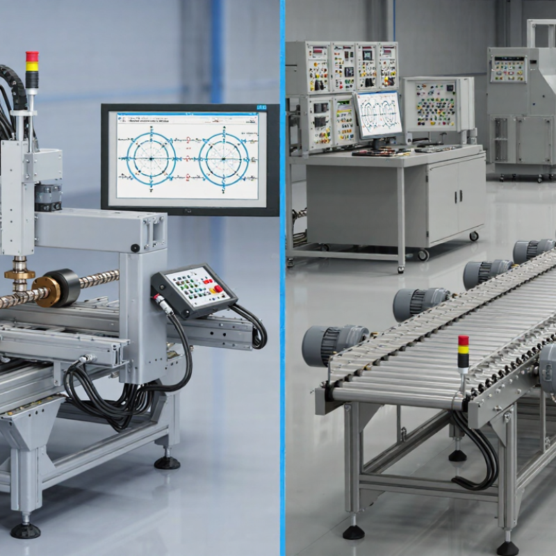
A motion system turns control commands into physical movement. It typically combines an actuator, drive, mechanical support, sensors, and a controller. The actuator supplies movement; guides help keep it steady, while sensors report position or speed. In a small camera slider, for example, a belt-driven carriage may travel along a rail. In a machine tool, the same basic idea may require rigid guides and precise feedback.
Motion systems are often grouped by the movement they produce. Linear systems move along a straight path, such as a lift raising a platform. Rotary systems turn around an axis, like a motor rotating a fan. Multi-axis systems coordinate several directions of movement, as a robotic arm does when reaching around an obstacle. Systems can also be described by how they create force: electric actuators are common for controlled positioning, while pneumatic or hydraulic actuators suit some fast or high-force tasks. These categories can overlap. A rotary motor may drive a linear stage through a screw or belt. That matters. A common mistake is choosing by speed alone; load, travel distance, accuracy, environment, and duty cycle also shape performance. Even a neat specification sheet cannot capture every vibration or alignment issue on a real installation.
How to Choose the Best Motion Systems for Your Needs - Understanding Motion Systems and Their Main Types
| Motion System Type | Typical Motion | Main Strengths | Key Trade-Offs | Common Applications | A Good Fit When... |
|---|---|---|---|---|---|
| Servo motor system | Rotary or linear motion with feedback control | Accurate positioning, strong dynamic response, and control of speed and torque | Typically requires a drive, feedback device, and tuning; can cost more than simpler systems | Robotics, packaging equipment, CNC machinery, and automated assembly | The application needs controlled acceleration, changing speeds, or repeatable positioning |
| Stepper motor system | Incremental rotary motion, often converted to linear travel | Simple digital control and predictable movement at low to moderate speeds | May lose synchronism if overloaded; torque generally decreases as speed increases | Small automation devices, laboratory instruments, and light-duty positioning stages | Loads and speeds are moderate, and a cost-conscious positioning solution is needed |
| Pneumatic actuator | Usually short-stroke linear motion; rotary versions are also available | Fast operation, straightforward mechanisms, and suitability for repetitive on/off movement | Compressed air is less rigid than a mechanical drive, so precise positioning can be challenging; air preparation and supply are required | Clamping, sorting, pick-and-place, and simple machine automation | The task mainly needs quick movement between end positions rather than fine positioning |
| Hydraulic actuator | High-force linear or rotary motion | Can deliver high force from a compact actuator and handle heavy loads | Needs hydraulic power equipment and fluid management; leakage, heat, and maintenance must be considered | Presses, lifting equipment, construction machinery, and heavy-duty manufacturing | High force or load capacity is more important than a clean, low-maintenance installation |
| Belt-driven linear actuator | Long-stroke linear travel | Can achieve high travel speeds over long distances with relatively low moving mass | Belt stretch and compliance can limit stiffness and positioning performance under load | Gantry systems, material handling, and long-travel transfer axes | Fast, long-distance travel is needed and extreme rigidity is not the primary requirement |
| Screw-driven linear actuator | Controlled linear travel using a lead screw or ball screw | Good positioning capability and useful force transmission; screw choice affects precision and efficiency | Maximum speed and practical travel length depend on screw design, support, and critical-speed limits; some designs need lubrication | Machine tools, inspection stages, and precision positioning equipment | A guided linear axis needs controlled positioning and moderate-to-high stiffness |
Selection note: Compare required travel, payload, speed, acceleration, positioning accuracy, duty cycle, environment, and maintenance needs. Actual performance depends on component sizing, control method, installation, and operating conditions.
Related Posts
-

10 Essential Tips for Optimizing Motion Systems Performance
-
What is a Motion Systems and How Do They Work?
-
Why Do Global Buyers Choose Motion Systems?
-

10 Essential Tips for Choosing Motor Control Solutions for Your Business?
-

How to Choose the Best Motion Solutions for Your Business?
-
Exploring the Science Behind Etel Motion and Its Impact on Modern Technology